
The day before our official “lockdown” began I woke up at about 6am to run to the hardware store and buy a smoker because that was the most important thing I could think of that I did not already have. This started a period of deep study into the finer points of barbecue and increased the collective mass of my social circle through the distribution of many batches of brisket and pulled pork. I quickly came to favor pulled pork as it uses one of the least expensive starting meats while producing a universally loved and incredibly versatile end result.
The only drawback is time as the restaurant supply packs Boston Butts (not that kind of butt) two to a cryopack, tipping the scales at around 10kg and requiring a total smoking time as long as 18 hours. Running a smoker manually is largely an exercise in airflow control, opening and closing the intakes to control the rate at which the wood and charcoal burns. This was not particularly difficult to handle even as a beginner but the changing states of both the external weather and the internal combustibles mean checking the smoker periodically the entire time it runs.
I like both sleep and delicious barbecue and endeavor to have both.

Existing Solutions
Other people have created automated control systems for smokers and they work quite well, but I thought I could improve on the state of the art in some specific ways. So far as I have been able to find, all existing smoker control systems operate by using a single PID loop whose process variable is the pit temperature and whose control variable is the PWM duty cycle of a fan. Network connected examples range from bluetooth to an entire Raspberry Pi running several applications.
I recognize that it is entirely the case that I could spend a few hundred dollars for someone’s existing system but that would not scratch my itches or entertain me the same way that spending a major chunk of my own time and even more dollars will.
Overall Goals
- Have a super sweet automation system for my smoker
- Learn more about controls theory - I’ve tuned and used PIDs, but never implemented a system from scratch
- Learn how to write firmware with a proper real time operating system instead of single-threaded arduino code
- Find novel solutions to improve the state of an art
- Develop a concept into a fully polished product
Controls Improvements
I believe a single PID is a coarse method for smoker control that does not take into account changing weather, gusts of wind, or the flow added by the smoker’s own convection. I thought about ways to work around this and the first thing that came to mind was the way fuel injected engines monitor airflow. Fuel injected engines are able to cope with a variety of complicating factors by constantly measuring the intake airflow and adjusting for it. An automotive mass airflow sensor (MAF) is a pretty common part and I even happened to have one laying around which I soldered up and tried blowing air through. I was not seeing the results I expected which led me to reading MAF datasheets from the manufacturer (Bosch, if I remember correctly) where I discovered that range of flows they intended were much higher than I had imagined and far above the range I suspect would be relevant to a smoker.
I began researching ways of measuring airflow and found a company named Sensirion making an entire range of mass airflow sensors aimed at the medical device industry. Their typical +/- 200 liters per minute seemed much better based on my very scientific measurement method of holding my hand above the exhaust vent of the smoker and seeing how windy it feels in normal use.
Connectivity Improvements
I have a strong distaste for a lot about the state of IoT, home automation, consumer cloud services, and the general crapification of the internet. I want the ability to remotely control and monitor my systems but am entirely unwilling to do that with a round trip out to the cloud or with software outside my control. I want to have the ability to operate entirely as a standalone piece of hardware with a functional user interface while also having the option to hook into standardized systems with standard protocols. No internet access needed, no slapdash phone app required, and no need to trust or involve outside parties.
I decided Espressif’s esp32 would be a good platform on which to build as it has enough power and connectivity for everything anticipated on this device while avoiding the bloat of even a smaller general purpose computer like a Raspberry Pi. Several friends had already been using esp32 with great results in a variety of projects and this would be a good way to learn my way around it as well as get started with freeRTOS and brush up on my rusty C++.
System Overview
1 2 3 4 5 6 7 8 9 10 11 12 13 14 15 16 17 18 |
               +-------------------------------+   +------------+
    AIRFLOW    |MASSFLOW SUBSYSTEM             |   | BLOWER FAN |
+------------> |                               |   +------------+
   MAF SENSOR  | PID 1                         |   PWM    ^
               |  PV: MEASURED AIRFLOW (L/MIN) +----------+
    AIRFLOW    |  CV: FAN PWM (% DUTY)         |  SETPOINT
  +----------> |  SETPOINT: AIRFLOW (L/MIN)    |
  | SETPOINT   +-------------------------------+
  |
  |            +-------------------------------+   +---------------+
  |            |COMBUSTION SUBSYSTEM           |   | PIT TEMP PROBE|
  |            |                               |   +---------------+
  |            | PID 2                         |   TEMP   |
  +------------+  PV: MEASURED PIT TEMPERATURE +<---------+
               |  CV: MASSFLOW SETPOINT (L/MIN)|          |
               |  SETPOINT: USER/PROG PIT TEMP |   +---------------+
               +-------------------------------+   |FOOD TEMP PROBE|
+---------------+ |
I broke my problem down into two distinct control loops - monitoring the actual airflow to be able to adjust fan power to hit a setpoint, and monitoring the temperatures in the smoker to decide how much airflow to request. It was not until much later that I learned this is called cascade control and is a normal method for handling situations like mine where parts of the process operate on very disparate time scales or are subject to different perturbations. In my case, wind may buffet around and change flow multiple times per second while the burning fuel pile and resultant smoker temperatures take minutes to change. Additionally because the MAF includes temperature compensation, cascading the controls in this way should help the system operate consistently across frigid nights and sweltering days.
It was validating to learn later that this is a Known Method, but highlights to me how control theory is covered with little depth in DIY type circles. There is an abundance of introductory information about PID loops, but very little accessible material for more nuanced and complex controls. This continues to be a point of struggle for me, and I may write more later to share the information I wish I had much earlier in the project.
Hardware Choices
Probes
While there are many options for temperature probes I knew I wanted to use ones that are common and cheap. Thermoworks is universally liked for their Thermapen, and sell a range of inexpensive thermistor probes that I use in my kitchen already. Their Pro-Series probes were my choice because of the fact that they are available in a number of formats including multiple penetration probe lengths as well as smokehouse blunt probes. All versions use the same thermistor under the hood so calibration would stay simple.
MAX6682

In researching how best to measure thermistors with the esp32 I found a lot of discussion about the poor quality of the onboard ADCs and how to work with it. I have found in the past that there are often integrated circuits for just about everything and this was happily true here. Maxim makes a thermistor-to-digital chip - MAX6682 - which comes in a tidy μMax-8 package has some cool features that are nice to not have to implement like minimizing self-heating by managing power to the thermistor. It uses a precision reference resistor (external to the chip, user selected) and does a little bit of linearization that is helpful for the mid-range of a given setup. The data interface is ‘SPI-compatible’ but I found it simple to just implement a library for this chip to handle its quirks. In particular, the behavior when polling too quickly is undefined and may return either junk data or old data, so my library enforces timing using a mutex. Something I found odd is the fact that I could only find two other people posting on the internet about this chip, neither of which even discussed actually using it.
Sensirion SFM3000
 Sensirion’s SFM3000 is a simple tool that communicates over I²C and provides a bidirectional airflow measurement in integer liters per minute (‘standard liters / min’, SLM). It implements CRC8, soft reset features, and is very easy to deal with. Under the hood it is temperature compensated and generally works well. It is the single most expensive component of the system at almost $90USD but enables the most unique feature of the entire project.
Accoutrement
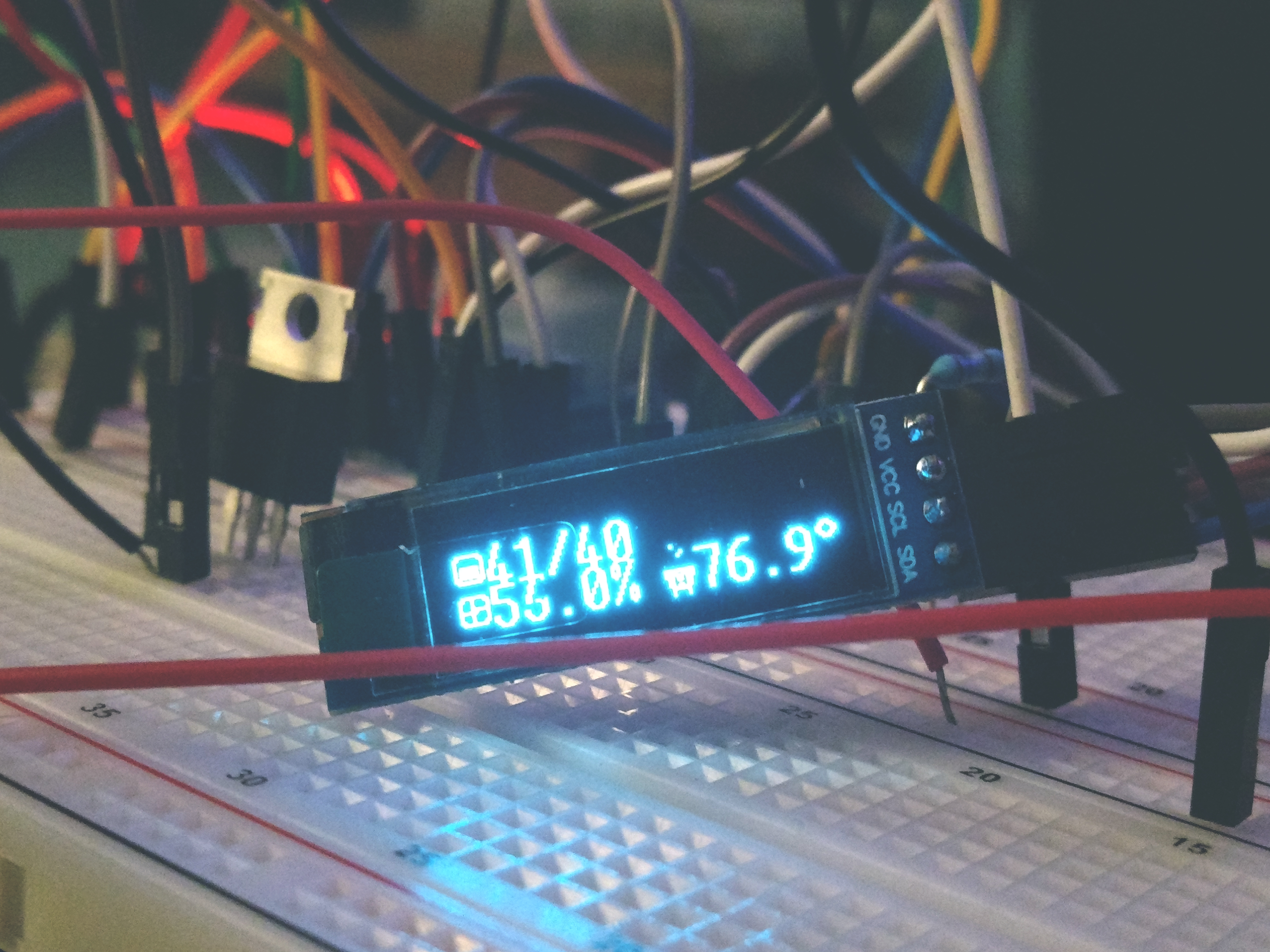
The initial prototype uses a few parts that will be familiar to many. An SSD1306-powered 128x32px OLED screen, FQP30N06L N-channel mosfets for power control, and a very plain vanilla esp32 dev board. I breadboarded the prototype knowing that I had a lot of uncertainty and wanted to be able to iterate quickly. It’s not hard to spin up boards but even a few days of extra time between changes would be a significant impediment and I hate to create trash piles of useless old prototype PCBs. While the very earliest assembly was done with a nest of 20cm breadboard jumpers, Ben Eater’s excellent series of videos on constructing complex systems on breadboards was inspirational for later rework and helped me keep things at least somewhat organized despite rewiring and reconfiguring frequently.
That’s all for this post. In the next one I’ll talk about calibration, testing, and the code.